Introduction
Ladder programming is the graphical representation of Boolean equations, combining contacts (inputs) and coils (outputs). The ladder diagram is delimited by bus lines on the left and right.
Graphical Components
The basic graphical components of a ladder diagram include:
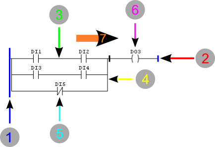
Figure 1 - Ladder Flow Diagram
- Left Bus
- Right Bus
- Horizontal Connection
- Vertical Connection
- Contact
- Coil
- Power Flow Direction
Buses
The editor is delimited on the left by a vertical line known as the left bus, and on the right by a vertical line known as the right bus.
Link Elements and States
Link elements can be horizontal or vertical. The status of link elements can be denoted by 1 or 0, corresponding to the literal Boolean value 1 (TRUE) or 0 (FALSE), respectively. The term link status must be synonymous with the term power flow.
The status of the left busbar can always be considered 1 (power source), while the right busbar is defined as state 0 (ground busbar).
A horizontal link element is indicated by a horizontal line. A horizontal link element transmits the status of the element immediately to the left to the element immediately to the right.
A vertical link element consists of vertical lines intersected by one or more horizontal links on each side.
The status of the vertical link represents the logical OR of the states of the horizontal links on the left side. That is, the state of the vertical links should be:
• 0, if the state of all horizontal links included to its left are 0, • 1, if the state of one or more horizontal links included to its left are 1.
The state of the vertical links is copied to all horizontal links associated to its right. The state of the vertical links is not copied to the horizontal links associated to its left.
Execution Control
The following figure shows how the ladder program is executed. The processor continuously executes a scan cycle. The cycle begins with the hardware input/output system, compiling the latest values of all input signals and writing their values to fixed memory regions.

Figure 2 - Execution Control
A - Inputs read into memory
B - Memory written to outputs
C - Scanning of the ladder lines
The lines of the ladder program are then executed in a fixed order, starting with the first line. During the program scan, new physical output values, as determined from the logic of the various ladder lines, are initially written to a region of output memory. Finally, when the ladder program has finished executing, all output values held in memory are written to the physical outputs by the hardware in a single operation.