|
MC_Power Axis Enable/Disable |
  
|
|
MC_Power Axis Enable/Disable |
|
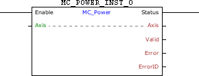
Block responsible for enabling/disabling the drive axis.
Ladder Representation
Execution Features
Program Memory Size |
40 Bytes |
Data Memory Size |
4 Bytes |
Block Structure
Variable Type |
Name |
Data Type |
Description |
VAR_IN_OUT |
Axis |
BYTE |
Selection of operation axis (0 - Real axis) |
VAR_INPUT |
Enable |
BOOL |
Block enabling |
VAR_OUTPUT |
Status |
BOOL |
Output enabling |
Valid |
BOOL |
Flag indicating validity of the output signals |
|
Error |
BOOL |
Error in the execution flag |
|
ErrorID |
WORD |
Identifier of the occurred error |
|
VAR |
MC_POWER_INST_0 |
MC_POWER |
Instance of access to block structure |
Operation
This block performs an Enable/Disable command of the Axis axis according to the Enable input, disabling it Enable is FALSE and enabling if Enable is TRUE.
|
NOTE! When the MC_Power block is used to enable/disable the real axis, no digital inputs must be programmed for the Enable function (option 1), or an Alarm A0120 may occur. |
When enabling the real axis for the first time, the drive may operate in grid position, depending on the value of parameter P0773. The position proportional gain (P0159) must be set to obtain a better drive performance.
When the real axis is disabled, the axis status will be Disabled. When enabling the real axis, the axis status will change to Standstill.
When EN has FALSE value, Status remains FALSE. The Status output is activated when the block finishes the execution successfully, remaining at TRUE level until Enable receives FALSE.
If there is any error in the execution, the Error output is enabled and ErrorID displays an error code according to the table below.
Code |
Description |
66 |
Drive in the "ErrorStop" status. |
71 |
P202 different from 4. |
Example in Ladder
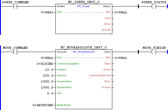
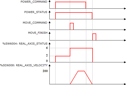
On the leading edge of POWER_COMMAND, the real axis is enabled and its status, the system marker REAL_AXIS_STATUS (%SW6004), is changed to Standstill (%SW6004 = 2). The Status output is set.
After the transition from 0 to 1 of MOTION_COMMAND, the MC_MotionAbsolut block is executed and the positioning for the position 10 revolutions starts. The axis status is changed to "Discrete Motion" (%SW3406 = 6).
While positioning is executed, POWER_COMMAND is reset. Since the BufferMode of the MC_Power is set to Buffered, the axis will be disabled only in the positioning completion.
When the positioning is finished, the Done output of the MC_MotionAbsolut block is set for 1 scan cycle and the axis is disabled (MC_Power.Enable = 0). The axis status changes to "Disable" (%SW6004 = 0).
Example in ST
The example below displays the instructions for applying the example above in the ST language.
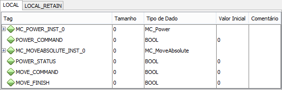
VAR POWER_COMMAND, POWER_STATUS, MOVE_COMMAND, MOVE_FINISH : BOOL; MC_POWER_INST_0 : FB_MC_Power; MC_MOVEABSOLUTE_INST_0 : FB_MC_MoveAbsolute; END_VAR
MC_POWER_INST_0.Enable := POWER_COMMAND; MC_POWER_INST_0(Axis:=0); POWER_STATUS := MC_POWER_INST_0.Status;
MC_MOVEABSOLUTE_INST_0.Execute := MOVE_COMMAND; MC_MOVEABSOLUTE_INST_0( Axis:=0, Continuousupdate:=0, Position:=LREAL#10.0, Velocity:=200.0, Acceleration:=1000.0, Deceleration:=1000.0, Jerk:=0.0, BufferMode:=0); MOVE_FINISH := MC_MOVEABSOLUTE_INST_0.Done;
|
|---|