|
Modbus TCP |
  
|
|
Modbus TCP |
|
This guide will help you set up the device as a Modbus TCP Client to connect with one or more Modbus TCP Servers.
|
IMPORTANT! Before using this service please be aware of the IMPORTANT NOTICE CYBERSECURITY AND COMMUNICATIONS |
The Modbus TCP client is configured through a configurator.
|
NOTE! For detailed information about how the client reads and writes data using Modbus TCP, see the specific device manual for Modbus TCP communication. |
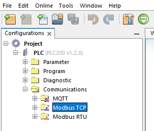
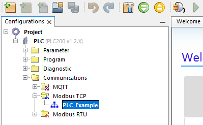
1) Expand the Communications directory.
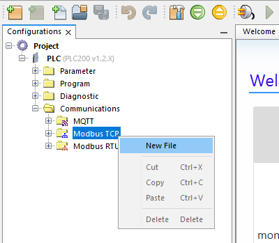
2) Right-click in Modbus TCP and click to create a new file.
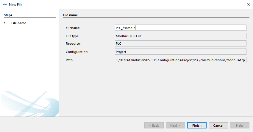
3) Enter a name to the new Modbus TCP configuration and click on Finish.
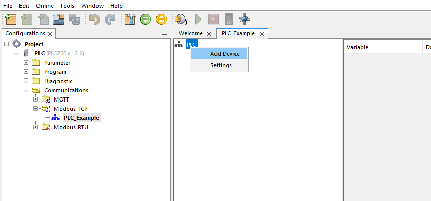
4) Double-click on the new Modbus TCP configuration file to open the configurator tab
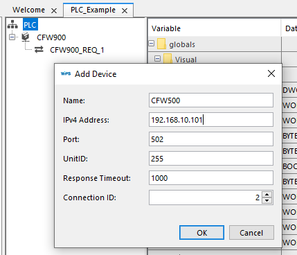
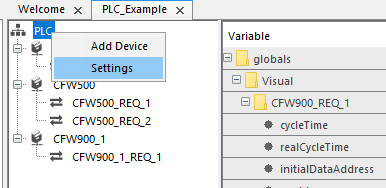
5) Right-click on the main network node PLC and click on the Add Device option.
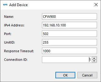
6) On the Add Device panel set up the device information:
| • | Name: Enter a name for the device, this name must be unique for any Modbus configurations; |
| • | IPv4 Address: The Modbus TCP device address. |
| • | Port: The Modbus TCP device port. |
| • | UnitID: The Modbus TCP device Unit ID. |
| • | Response Timeout: The timeout to connect to the device. |
| • | Connection ID: The connection ID to this Modbus device. |
|
NOTE! Each device has a limit of simultaneous connections, in other words, Connection IDs. If the network has more devices (Modbus Servers) than this limit. The devices will need to share connections ID. |
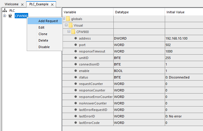
7) After setting up a device, right-click on it to add requests.
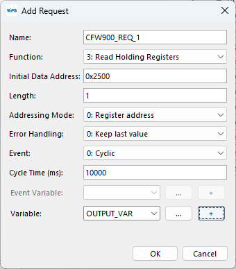
8) On Add Request panel set up the request informations:
| • | Name: A name for request, this name must be unique for any Modbus configurations. |
| • | Function: |
1: Read Coils
2: Read Discrete Inputs
3: Read Holding Registers
4: Read Input Registers
5: Write Single Coil
6: Write Single Register
15: Write Multiple Coils
16: Write Multiple Registers
| • | Initial Data Address: The address or number of register or coil, depends of the Addressing Mode set up. |
| • | Length: Number of registers or coils to be read or written. |
| • | Addressing Mode: |
0: Register address - Define that the Initial Data Address set up the register address;
1: Register number (Modicon) - Define that the Initial Data Address set up the register number, first, second, etc.
| • | Error Handling: |
0: Keep last value
1: Set to zero
| • | Event: |
0: Cyclic
1: Rising Edge
2: Initialization
| • | Cycle Time: Request cyclic execution time |
| • | Event Variable: Variable for Rising Edge event. |
| • | Variable: Input or Output variable, depends on the Modbus function type |
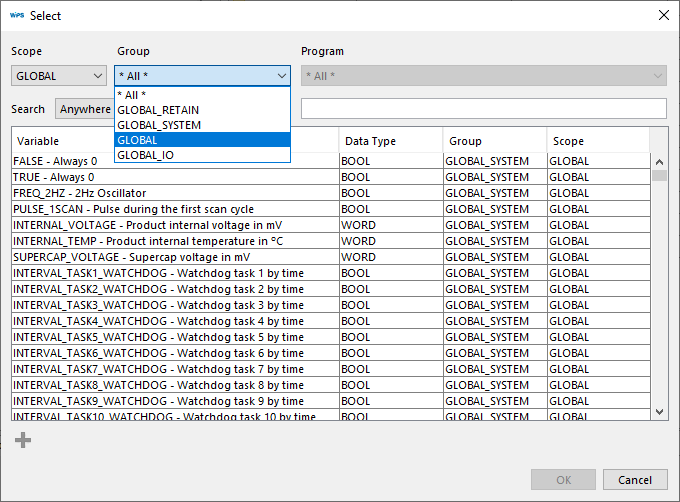
8.1) To create a Global Variable to request click on the Ellipsis points button and select Global's Scope and Group.
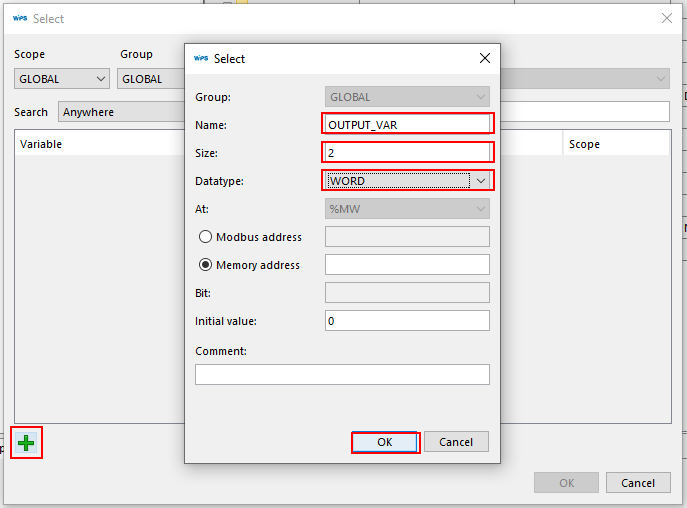
8.2) Click on the Add button to open the Variable panel and enter a name to the new Variable, a size according with Request Length and the variable Datatype, to conclude click on OK button
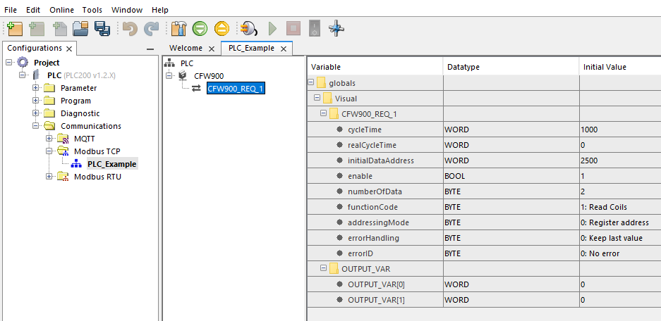
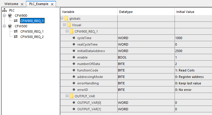
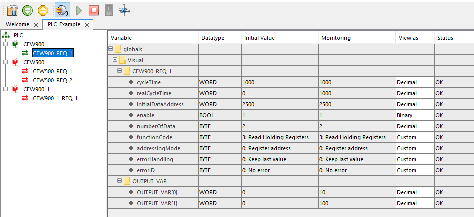
9) A request will be created, on the right split window the information about the selected request or device is showed.
10) Repeat the steps to create the Modbus TCP network.
|
NOTE! The Modbus configurator will suggest a new Connection ID. Change it manually if necessary. |
|
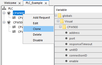
NOTE! If your network has more than one device with the same requests you can Clone an existent device althout create a new one. |
10.1) To Clone a device, right-click on it and choose the Clone option.
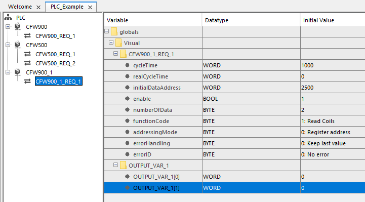
|
NOTE! The device will be cloned with the same requests, new variables will be created for this new device. |
|
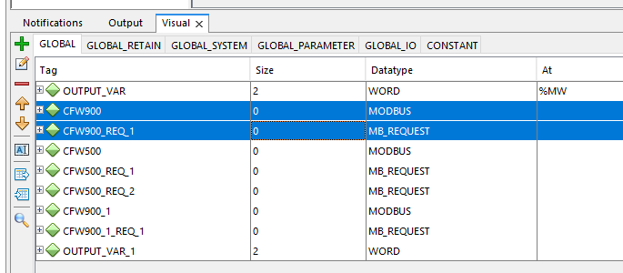
NOTE! When you use the Modbus Configurator to create the Modbus Network the configurator will create global variables of datatype MODBUS to devices and variables of datatype MB_REQUEST to requests. |
11) The configuration must be compiled before downloading to the device.
|
NOTE! Any doubt about this process access the COMPILE session. |
|
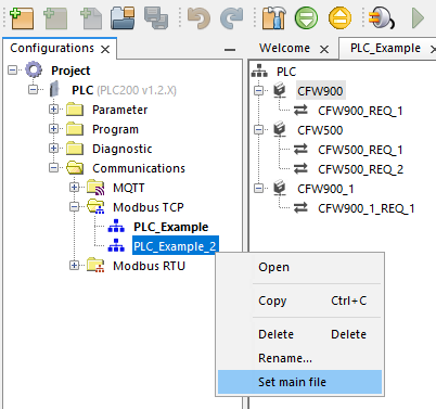
NOTE! Is possible to create more than one Modbus TCP configuration but just one can be selected per device. |
11.1) In cases where there is more than one Modbus TCP configuration, click the right button and select the main file.
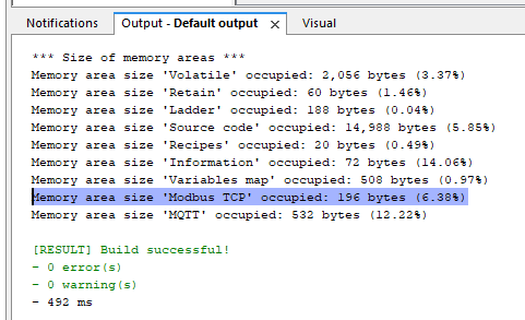
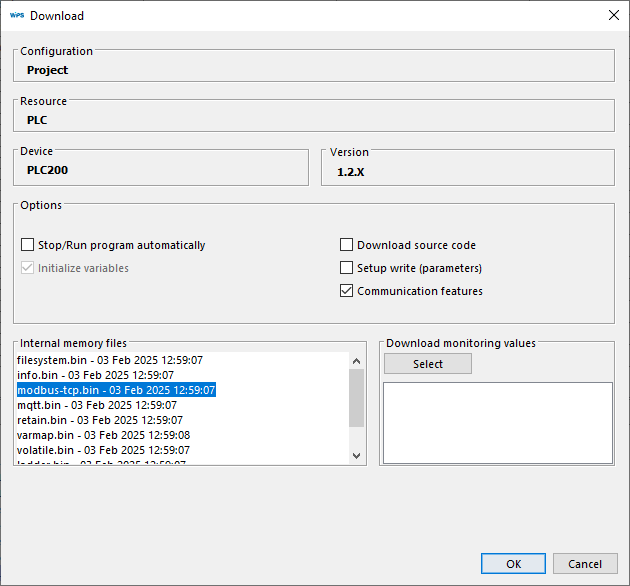
12) After compile the project, click on download button, check the option Communication features and observe if "modbus-tcp.bin" is on Internal memory files list.If yes, click in OK button to start the download.
Other functions:
A) Monitoring
A.1) The Modbus TCP communication can be monitored using the configurator panel.
B) Disable and Enable
|
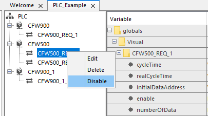
NOTE! On Modbus configurator is possible to Disable and Enabled devices and request before compile the project. |
B.1) To disable a request, click with right button on it and select Disable.
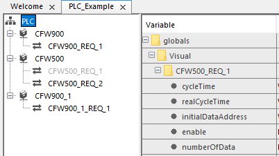
B.2) Verify that the request will be disabled on the network.
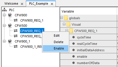
B.3) To enable, click on the disabled request and select Enable.
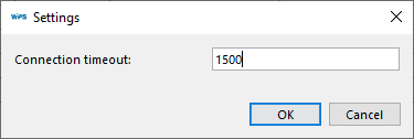
C) General client settings
C.1) To change the Connection Timeout, click with right button on the main node PLC and select Settings.
C.2) Set up the Connection Timeout in milliseconds.