|
Alarms |
  
|
|
Alarms |
|
Overview
Alarms are important tools in the automation of processes, allowing the user to monitor their plant by checking critical points and signaling to the operator.
Configurable alarms in PLC300 are programmed by the user, being activated by a bit marker that can be enabled by the Ladder program.
Internal alarms are relative to some hardware components that occupy the internal memory.
The alarms are configured through the Alarm Config screen accessed by the project folders:
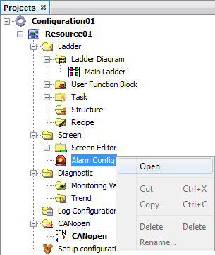
Alarm Configuration
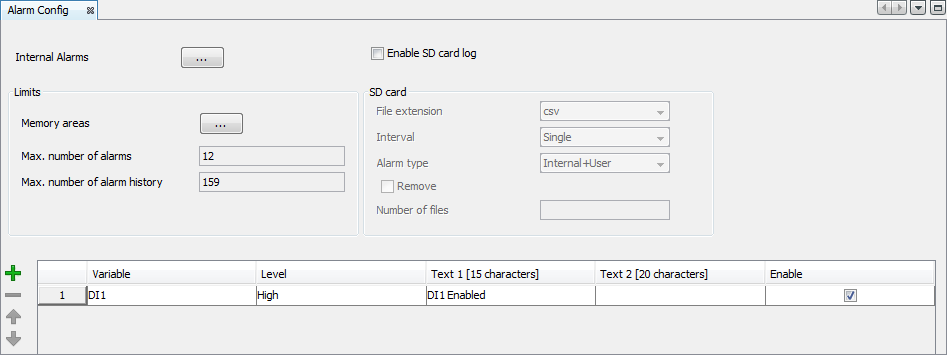
In the alarm configuration window, it is configured:
| • | Internal alarms: Alarms generated by the device that can be enabled or disabled by the user; |
| • | Limits: Maximum area taken by the user’s alarms and by the alarm history; |
| • | SD card: Alarm storage configurations in the SD card; |
| • | User’s alarm table: Table for configuration of the alarms activated through the variables of the device. |
Internal alarms
The internal alarms are alarms generated by the device that can be enabled or disabled by the user. In order to access the internal alarm configuration window it is necessary to press the button ![]() in the alarm window.
in the alarm window.
The PLC 300 has six internal alarms, five o which can be enabled by the user:
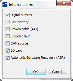
| • | Digital Output Fault: Indicates that some problem is occurring in some of the outputs DO1 and DO8. |
| • | Broken Wire: Current below 2 mA, when the AI1 analog input is in current mode 4 to 20mA. |
| • | Encoder Fault: One of the signals of the encoder is missing. |
| • | Supply of CAN: Power supply missing in the CAN interface. |
| • | SD card: This alarm occurs when there is a problem in the writing or reading of the SD card. The most common problems are: SD card missing, card protected against writing and formatting of the file system different from FAT32 . |
Limits
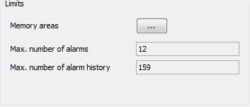
In the field limits, the maximum area taken by the user’s alarms and by the alarm history is configured. The button ![]() , in the limit field, opens the memory area configuration window. In this window you can configure the size of the memory area that the user’s alarms and the user’s history must take.
, in the limit field, opens the memory area configuration window. In this window you can configure the size of the memory area that the user’s alarms and the user’s history must take.
The size that the user’s alarm takes in the memory is calculated through the formula:
Alarm size (bytes) = 32 + (80 x number of alarms)
The size that the alarm history takes in the memory is calculated through the formula:
History size (bytes) = 32 x number of histories
SD Card
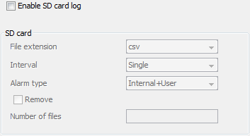
The SD card option, when enabled, configures the storage characteristics of the alarms in the SD card. The storage of alarm files has the following options:
| • | File extension: Format in which the alarms will be stored in the SD card. The options are: |
| o | txt: text with formatting of easy comprehension for the users. |
| o | csv (comma separated value): comma separated values, generally used in spreadsheets. |
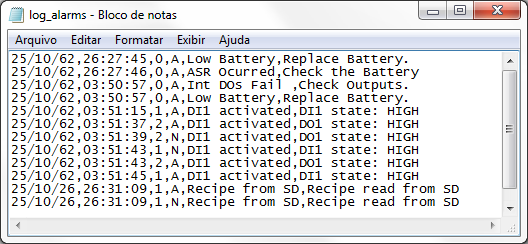
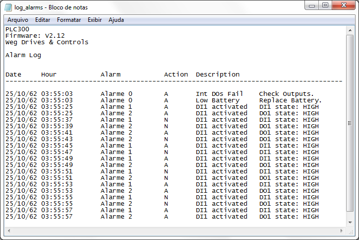
The values stored are date, time, alarm (0 – internal, 1 – user’s alarm), action (A – actuated and N – standardized) and description.
| • | Interval: In the interval field, it is configured the duration time of the recording of the data in a single file. The options of this field are the following: |
| o | Single: The data will be recorded in a single file. |
| o | Daily: The data are recorded in a file a day. The recording of a new file begins whenever the day on the clock of the device changes. The file is recorded with a suffix containing the day, month and year on which its recording began. |
| o | Monthly: The data are recorded in a file a month. The recording of a new file begins whenever the month on the clock of the device changes. The file is recorded with a suffix containing the month and year in which its recording began. |
| o | Annual: The data are recorded in a file a year. The recording of a new file begins whenever the year on the clock of the device changes. The file is recorded with a suffix containing the year in which its recording began. |
| • | Alarm type: Alarm values that will be stored in the SD card. They can be of the User type to store only the alarms configured by the user or User+Internal to store the alarms configured by the user and the internal alarms. |
| • | Remove: When this option is selected, the dialog box Number of files is enabled, allowing to input a whole number. This number represents the number of files that will be maintained in the SD card. Whenever a file is created daily, monthly or annually, the number of files created for this alarm is checked and then the older files are removed. |
User’s alarm table
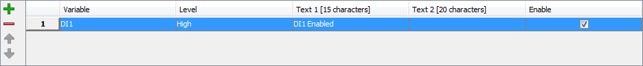
In the user’s alarm table, the alarms activated are configured through variables of the devices with texts edited by the user. The alarm table has four fields to be filled out:
| • | Marker: Bit marker that activates the alarm. Global variable of the Boolean type. |
| • | Enable: Enable/Disable alarm option. |
| • | Edge: Transition edge in which the alarm will be activated. The possible values are positive (from 0 to 1) or negative (from 1 to 0). |
| • | Text 1: Text for the alarm message. This field can contain at most 15 characters. This text will be viewed in the active alarm list and alarm history. |
| • | Text 2: Text for alarm message description. This field can contain at most 20 characters. This text will be viewed in the detailed description of the active alarms and alarm history. |
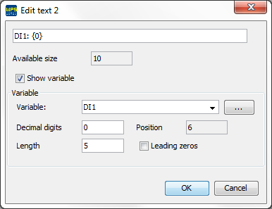
The view and configuration fields of text 2 are the followings:
| • | Available space: Number of available characters for editing text. The maximum number of characters is twenty (if the option show variable is selected, the space taken by the variable is added to the characters taken by the text). |
| • | Show variable: It enables the option to show variable in text 2 of the alarm. If the text does not have the variable location marking {0}, it is automatically added. |
| • | Variable: Variable that will be displayed in the text, in the position and format defined in the fields: position, decimal digits, length and filling with zeros. |
| • | Decimal digits: Number of decimal digits for displaying the variable. |
| • | Position: Position in which the variable will be inserted. This is a read-only field and it is updated at each position change. |
| • | Length: Space that will be reserved for displaying the variable. The user must take care to reserve enough space for displaying signal and decimal point, if necessary. |
| • | Leading zeros: it fills the spaces that are empty between the configured length and the variable size with zeros. |