|
Introduction |
  
|
|
Introduction |
|
Ladder Programming is the graphical representation of boolean equations combining contacts (input arguments) with coils (output results).
Ladder programming enables testing and modifying data by standard graphical symbols. These symbols are positioned in the Ladder diagram in a way that is similar to a line of a logic diagram with relays. The Ladder diagram is delimited on the left and on the right by busbar lines.
Graphical Components
The basic graphical components of a Ladder diagram are shown below.
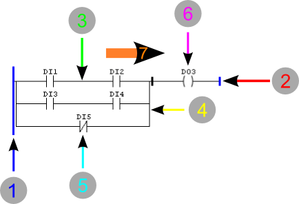
Figure 1: Ladder Working Flow
| 1. | Left busbar |
| 2. | Right busbar |
| 3. | Horizontal connection |
| 4. | Vertical connection |
| 5. | Contact |
| 6. | Coil |
| 7. | Power flow |
Busbars
The editor is delimited on the left by a vertical line known as left busbar, and on the right by a vertical line known as right busbar.
Connection Elements and States
The connection elements may be horizontal or vertical. The state of the connection elements may be denoted by 1 or 0, corresponding to the literal Boolean value 1 or 0, respectively. The term connection state must be synonymous with the term power flow.
The state of the left busbar may always be considered 1. No states are defined on the right busbar.
The horizontal connection element must be indicated by a horizontal line. A horizontal connection element transmits the state of the element immediately on the left to the element immediately on the right.
The vertical connection element must consist of vertical lines intersected by one or more horizontal connections on each side.
The state of the vertical connection must represent the logical OR of states 1 of horizontal connections on the left side, i.e. the state of the vertical connections must be:
| • | 0 if the state of all horizontal connections included on its left is 0, |
| • | 1 if the state of one or more horizontal connections included on its left is 1. |
The state of the vertical connections must be copied to all associated horizontal connections on its right.
The state of vertical connections must not be copied to associated horizontal connections on its left.
Execution Control
The following figure shows how the program in Ladder is executed. The card continually runs a Scanning cycle. The cycle begins when the I/O System in the hardware compiles the last values of all input signals and records those values in fixed areas of the memory.
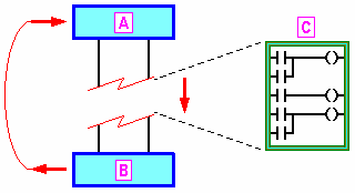
Figure 2: Execution Control
A - Inputs read to the memory
B - Memory written in the Outputs
C - Scanning of Ladder lines
The lines in the Ladder program are then run in a fixed order, starting with the first line. During program scanning, new values for physical outputs, as determined by the logic of several Ladder lines, are initially written to an area of the output memory. Finally, when the Ladder program has finished running, all output values retained in the memory are inscribed in the physical outputs by the hardware in a single operation.