|
CTD |
  
|
|
CTD |
|
Countdown block of input pulses.
Ladder Representation
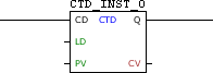
Block Structure
Variable Type |
Name |
Data Type |
Description |
VAR_INPUT |
CD |
BOOL |
Pulse identifier |
LD |
BOOL |
Loads the value of PV in CV |
|
PV |
WORD UINT |
Value of initial configuration |
|
VAR_OUTPUT |
Q |
BOOL |
Counter zeroed flag |
CV |
WORD UINT |
Current count value |
|
VAR |
CTD_INST_0 |
CTD |
Instance of access to block structure |
|
NOTE!
Some devices allow you to configure user parameters, but these need to be configured for use in the fields PV and CV, where it is necessary to select a compatible data type (WORD or UINT). For more information refer to the corresponding topic. |
Operation
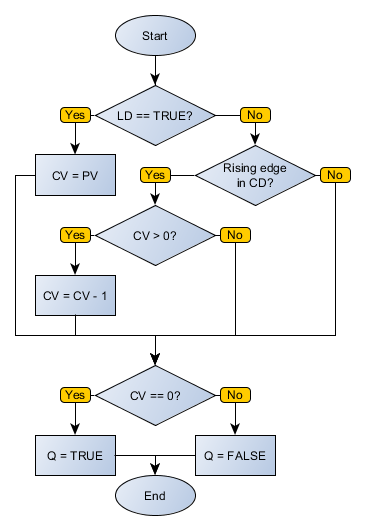
When this block identifies a leading edge in CD, it decrements the CV variable until it is zero. While CV equals zero, the output Q remains at TRUE level. By detecting high-level LD, the block loads the PV value in CV.
Block Flowchart
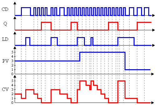
Operation Diagram
Example in Ladder

The above example shows the initial conditions of routine. As CV has a value of zero, the Q output is enabled.
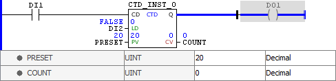
The value of the PV variable was changed to 20, but not yet loaded.
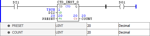
By identifying TRUE level in LD, the block loads the PV value to CV. Since this value is greater than zero, the Q output is disabled.
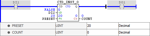
At each leading edge identified in CD, the value of COUNT is decremented until it reaches zero, when the Q output is enabled.
Example in ST
The example below displays the instructions for applying the example above in the ST language.
VAR PRESET : UINT := 20; COUNT : UINT; CTD_INST_0 : FB_CTD; END_VAR
CTD_INST_0.CD := DI1; CTD_INST_0(LD:=DI2, PV:=PRESET); COUNT := CTD_INST_0.CV; DO1 := CTD_INST_0.Q;
|
|---|