|
PID |
  
|
|
PID |
|
Block that performs the function of a discrete PID controller. From the input variables, it calculates the corresponding controller output.
Ladder Representation
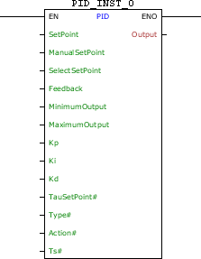
Block Structure
Variable Type |
Name |
Data Type |
Description |
VAR_INPUT |
EN |
BOOL |
Block enabling |
SetPoint |
REAL |
Automatic reference (pre-control) |
|
ManualSetPoint |
REAL |
Forced reference (post control) |
|
SelectSetPoint |
BOOL |
Selects which reference to use |
|
Feedback |
REAL |
Feedback loop variable |
|
MinimumOutput |
REAL |
Minimum value of the controller output |
|
MaximumOutput |
REAL |
Maximum value of the controller output |
|
Kp |
REAL |
Proportional gain |
|
Ki |
REAL |
Integral gain |
|
Kd |
REAL |
Derivative gain |
|
TauSetPoint# |
REAL |
Time constant of the automatic reference in put filter |
|
Type# |
BYTE |
Controller type |
|
Action# |
BYTE |
Control action |
|
Ts# |
UINT |
Sampling time [ms] |
|
VAR_OUTPUT |
ENO |
BOOL |
Output enabling |
Output |
REAL |
Controller output |
|
VAR |
PID_INST_0 |
PID |
Instance of access to block structure |
Operation
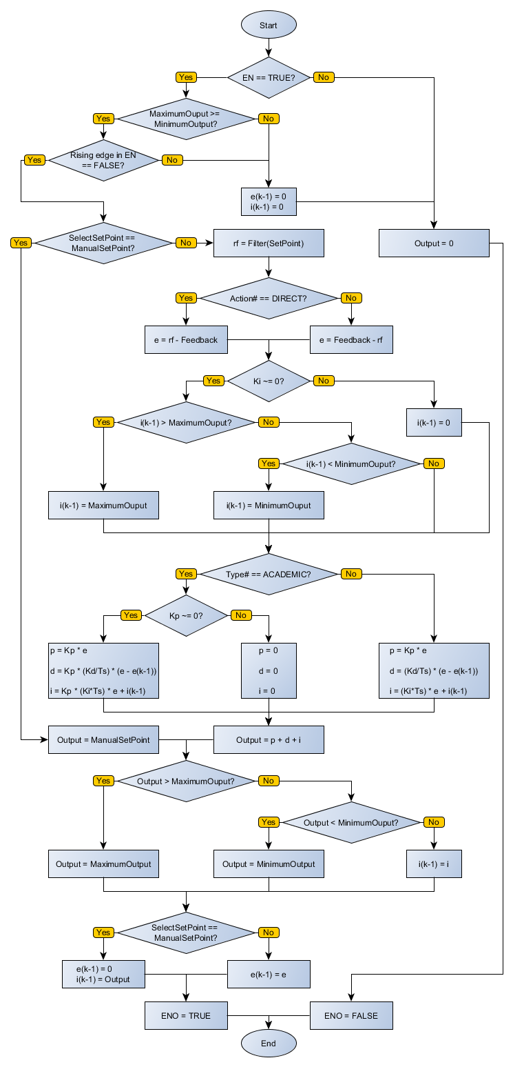
On the positive transition edge in EN, Output receives zero value, and the block executes its functionality as EN is at TRUE level.
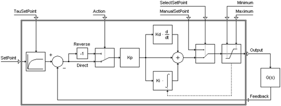
When enabled, this block performs a routine PID control with the Kp, Ki and Kd parameters chosen. The PID topology used may be the Academic or Parallel, depending on what is chosen in Type#.
Academic Form:
Parallel Form:
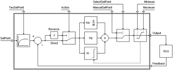
The levels of the output signal of the controller are saturated at value MinimumOutput and MaximumOutput. The SelectSetPoint input level FALSE causes the SetPoint reference be adopted, allowing the controller maintains control over the process. When SelectSetPoint goes to TRUE level, the controller has no more domain, and ManualSetPoint becomes to be considered the output signal of the controller.
Action# will define the feedback operation. If Action# is DIRECT, the operation will be SetPoint – Feedback. If Action# is REVERSE, the operation will be Feedback – SetPoint.
Feedback receives the process variable considered as the plant output. Ts# receives the sampling time for the controller and # TauSetPoint receives the time constant for the input filter of the automatic reference.
When EN has FALSE value, Output remains unchanged.
The ENO value forwards to the next Ladder block the EN value after the operation is completed.
|
NOTE! Effects of the alteration of gains on the process
|
|
NOTE! How to improve the performance of the process through the adjustment of gains (valid for the Academic PID)
|
Block Flowchart
Example in Ladder
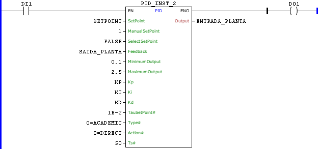
The above example creates a loop of a digital PID form with sampling time 50 ms, using the constants KP, KI and KD for control. Automatic reference SETPOINT, filtered by a first order filter with time constant of 0:01 is used. The error signal is calculated as the difference between the filtered reference and variable SAIDA_PLANTA. The controller output is saturated between the values 0.1 and 2.5 and sent to the variable ENTRADA_PLANTA.
Example in ST
The example below displays the instructions for applying the example above in the ST language.
VAR SETPOINT, SAIDA_PLANTA, ENTRADA_PLANTA : REAL; KP : REAL := 6.2; KI : REAL := 1.3; KD : REAL := 1.8; PID_INST_2 : FB_PID; END_VAR
PID_INST_2.EN := DI1; PID_INST_2( SetPoint:=SETPOINT, ManualSetPoint:=1, SelectSetPoint:=FALSE, Feedback:=SAIDA_PLANTA, MinimumOutput:=0.1, MaximumOutput:=2.5, Kp:=KP, Ki:=KI, Kd:=KD, TauSetPoint:=0.01, Type:=0, Action:=0, Ts:=50); ENTRADA_PLANTA := PID_INST_2.Output; DO1 := PID_INST_2.ENO;
|
|---|