|
USERERR User-generated error |
  
|
|
USERERR User-generated error |
|
Block that generates an alarm or fault with the number programmed by the user.
Ladder Representation
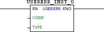
Block Structure
Variable Type |
Name |
Data Type |
Description |
VAR_INPUT |
EN |
BOOL |
Block enabling |
CODE |
WORD UINT |
Error code generated (950 - 999) |
|
TYPE |
BYTE |
Error type generated (0 - Alarm) (1 - Fault) |
|
VAR_OUTPUT |
ENO |
BOOL |
Success in the generation of error |
VAR |
USERERR_INST_0 |
USERERR |
(*) Instance of access to block structure |
|
NOTE! (*) USERERR_INST_0 instance must be configurated to SCA06 and LDW900. |
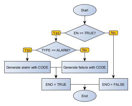
Operation
When this block has a TRUE value in EN, it generates an alarm or equipment failure, depending on the type defined in TYPE with CODE code.
The value of ENO informs if the generation of alarm or fault has been executed successfully.
Block Flowchart
Example in Ladder
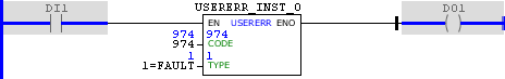
The above example, when identifying TRUE level in DI1, generates a fault with the code 974 and sets the DO1 output.
USERERR table configuration
On devices that have text-based HMI, messages can be configured through an editor. To access the editor, right click on the USERERR block and select the "Edit USERERR Table" option.
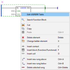
The texts configured in the table will be displayed on the HMI when the block USERERR is enabled.

After editing the table, select the argument CODE of the block equal to the CODE column of the table.
Example in ST
The example below displays the instructions for applying the example above in the ST language.
VAR USERERR_INST_0 : FB_USERERR; END_VAR
DO1 := USERERR_INST_0(EN:=DI1, CODE:=974, TYPE:=1);
|
|---|