|
MW_PlcChangeSpeed |
  
|
|
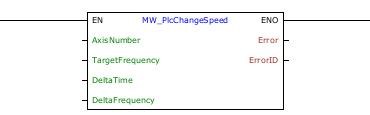
MW_PlcChangeSpeed |
|
Speed control block to be used in conjunction with the MW_PlcSpeed block.
This block allows changing the speed set by an active MW_PlcSpeed block at the selected output. If there are no active MW_PlcSpeed blocks for the selected output, this block generates an error.
Ladder Representation
Block Structure
Variable Type |
Name |
Data Type |
Description |
VAR_INPUT |
EN |
BOOL |
Block enabling |
AxisNumber |
CONST |
Selected axis |
|
TargetFrequency |
DWORD DINT |
Final pulse frequency [Hz] |
|
DeltaTime |
DWORD |
Step time until reaching the target frequency [ms] |
|
DeltaFrequency |
DWORD DINT |
Frequency variation of each step [Hz] |
|
VAR_OUTPUT |
ENO |
BOOL |
Output enabling |
Error |
BOOL |
Indicates that an error occurred when calling the block |
|
ErrorID |
BYTE |
Indicates the error generated |
|
VAR |
MW_PlcChangeSpeed_INST_0 |
MW_PlcChangeSpeed |
Instance of access to block structure |
Operation
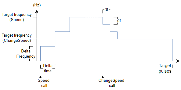
When the EN input changes from FALSE to TRUE, the block adjusts the pulse frequency of the selected axis, starting from the current frequency and moving towards the target frequency.
At each time step (deltaTime), the frequency is increased by deltaFrequency until reaching the desired frequency (targetFrequency).
This block works as a complement to the MW_PlcSpeed block, only allowing you to change the initially defined frequency.
The MW_PlcSpeed block continues to be responsible for monitoring the number of pulses generated or disabling the output if disabled.
Look at the help of the MW_PlcSpeed block to check the limitations of the steps.
|
NOTE! There must be an active MW_PlcSpeed block controlling the output. |
The figure below shows the output behavior when enabling the block.
If there is any error in the execution, the Error output is enabled and ErrorID displays an error code according to the table below.
Code |
Description |
0 |
Executed successfully |
1 |
Speed control not started |
2 |
Invalid input data |
3 |
Configuration error |
Example in Ladder
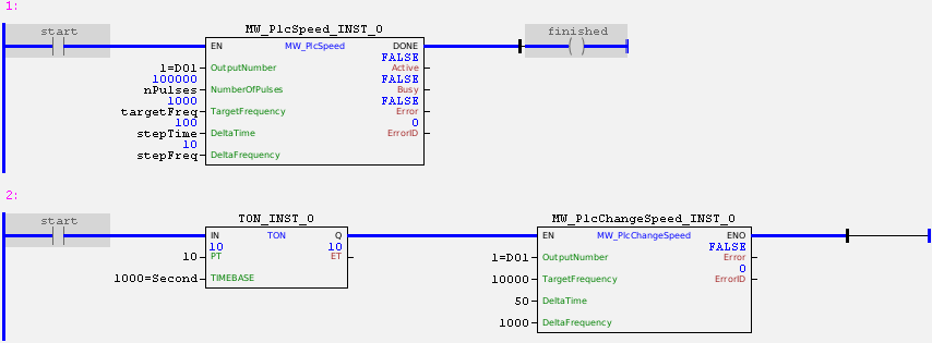
In the example above, the "start" contact enables the pulse signal on DO1 with an initial frequency of 0 Hz. The frequency will be incremented by 10 Hz every 100ms until it reaches 1000 Hz.
In parallel, the "start" contact starts a 10-second counter which, at the end of the time, will cause the DO1 pulse frequency to be changed to 10000 Hz with steps of 50 ms and 1000 kHz.
In the total execution of MW_PlcSpeed_INST_0, 100000 pulses will be sent to the output, regardless of how many times the frequency has been changed. Once the block has been completed successfully, the block output is activated.
Example in ST
The example below displays instructions for applying the functional example in ST language.
VAR nPulses : DWORD := 100000; targetFreq : DWORD := 20000; stepFreq : DWORD := 2000; stepTime : DWORD := 100; start : BOOL := 0 ; finished : BOOL; MW_PlcSpeed_INST_0 : FB_MW_PlcSpeed; MW_PlcChangeSpeed_INST_0 : FB_MW_PlcChangeSpeed; TON_INST_0 : FB_TON; END_VAR
MW_PlcSpeed_INST_0.EN := start; MW_PlcSpeed_INST_0( OutputNumber:=1, NumberOfPulses:=nPulses, TargetFrequency:=targetFreq, DeltaTime:=stepTime, DeltaFrequency:=stepFreq); finished := MW_PlcSpeed_INST_0.DONE;
TON_INST_0.IN := start; TON_INST_0(EN:=10, TIMEBASE:=1000);
MW_PlcChangeSpeed_INST_0.EN := TON_INST_0.Q; MW_PlcChangeSpeed_INST_0( OutputNumber:=1, TargetFrequency:=10000, DeltaTime:=50, DeltaFrequency:=1000);
|
|---|