|
MW_PlcChangeRamp1 |
  
|
|
MW_PlcChangeRamp1 |
|
Block to change the default ramp and speed of the axes in the axis control mode.
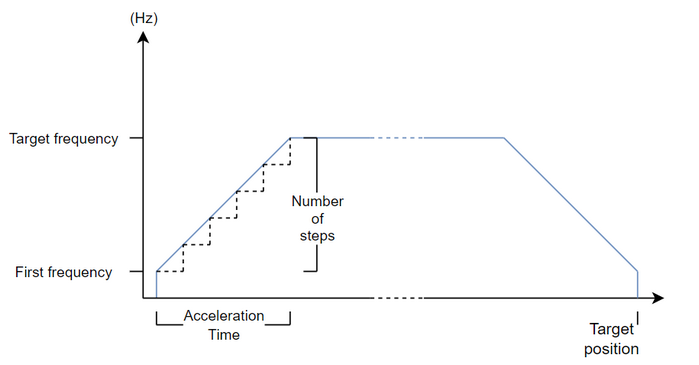
The axis control blocks (MW_PlcMoveAbsolute and MW_PlcMoveRelative) have a standard ramp with the following characteristics:
| • | Acceleration time: 100 ms; |
| • | Number of steps for acceleration: 20; |
| • | Starting frequency: 0 Hz; |
| • | Final frequency: 10 kHz. |
This block allows you to change these default values.
Ladder Representation

Block Structure
Variable Type |
Name |
Data Type |
Description |
VAR_INPUT |
EN |
BOOL |
Block enabling |
AxisNumber |
CONST |
Selected axis |
|
FirstFreq |
DWORD DINT |
Starting pulse frequency [Hz] |
|
TargetFreq |
DWORD DINT |
Final pulse frequency [Hz] |
|
AccelerationTime |
DWORD |
Ramp time [ms] |
|
NumberOfSteps |
BYTE USINT |
Step to increase frequency |
|
VAR_OUTPUT |
ENO |
BOOL |
Output enabling |
Busy |
BOOL |
Indicates that the axis is moving |
|
Error |
BOOL |
Indicates that an error occurred when calling the block |
|
ErrorID |
BYTE |
Indicates the error generated |
|
VAR |
MW_PlcChangeRamp1_INST_0 |
MW_PlcChangeRamp1 |
Instance of access to block structure |
Operation
When the EN input changes from FALSE to TRUE (rising edge), the block changes the default ramp of the selected axis (axisNumber) to the input values.
The block will only change values if the selected axis is stopped; otherwise, the "Busy" output will be TRUE.
The ramp will be changed for both control blocks of 1 axis (MW_PlcMoveAbsolute1 and MW_PlcMoveRelative1) and control blocks of two axes simultaneously (MW_PlcMoveAbsolute2 and MW_PlcMoveRelative2).
The final frequency cannot be 0 Hz.
The final frequency must be greater than the initial frequency.
The minimum ramp time is 1 ms. If a smaller value is defined for the block, the block will automatically consider 1 ms.
The minimum number of steps is 1. If a smaller value is defined for the block, the block will consider 1 automatically.
|
NOTE! The minimum number of steps per step is 2. If this requirement is not met, the ramp will not be generated.
To verify if the requirement is being met, consider:
delta_t_ms = AccelerationTime / NumberOfSteps (time per step in ms) delta_t_s = delta_t_ms / 1000 (time per step in seconds) delta_f = (TargetFreq - FirstFreq) / NumberOfSteps (frequency variation per step) The lowest frequency, lowerFrequency, used in the ramp will be FirstFreq if FirstFreq is different from 0; otherwise, the lowest frequency in the ramp will be delta_f itself.
Thus, if the following condition is true, it means the minimum requirement of 2 steps per step is not being met:
delta_t_s * lowerFrequency < 2
That is, the user must ensure that:
delta_t_s * lowerFrequency >= 2 |
The figure below shows the behavior of the ramp according to the configured values.
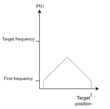
If the desired position is very close to the current one, the block will limit the maximum frequency, maintaining the configured acceleration, as shown in the figure below.
If there is any error in the execution, the Error output is enabled and ErrorID displays an error code according to the table below.
Code |
Description |
0 |
Executed successfully |
1 |
Axis control not enabled |
2 |
Invalid ramp |
3 |
Configuration error |
Example in Ladder
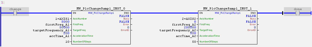
In the example above, the "change" contact changes the value of the standard ramps of two product axes (assuming that the control of these two axes is enabled).
A rampa do eixo 1 será alterado para:
| • | Acceleration time: 200 ms; |
| • | Number of steps for acceleration: 10; |
| • | Starting frequency: 5 kHz. |
| • | Final frequency: 50 kHz. |
The axis 2 ramp will be changed to:
| • | Acceleration time: 500 ms; |
| • | Number of steps for acceleration: 50; |
| • | Starting frequency: 0 Hz. |
| • | Final frequency: 200 kHz. |
In other words, all motion control commands for these axes from now on will have this ramp by default, both for 1-axis control blocks and for 2-axis control blocks (observing the limits of each one).
Example in ST
The example below displays instructions for applying the functional example in ST language.
VAR firstFreq_A1 : DWORD := 5000; targetFreq_A1 : DWORD := 50000; accTime_A1 : DWORD := 200; firstFreq_A2 : DWORD := 0 ; targetFreq_A2 : DWORD := 200000; accTime_A2 : DWORD := 500; change : BOOL := 0 ; done : BOOL; MW_PlcChangeRamp1_INST_0 : FB_MW_PlcChangeRamp1; MW_PlcChangeRamp1_INST_1 : FB_MW_PlcChangeRamp1; END_VAR
MW_PlcChangeRamp1_INST_0.EN := change; MW_PlcChangeRamp1_INST_0( AxisNumber:=1, FirstFreq:=firstFreq_A1, TargetFreq:=targetFreq_A1, AccelerationTime:=accTime_A1, NumberOfSteps:=10);
MW_PlcChangeRamp1_INST_1.EN := MW_PlcChangeRamp1_INST_0.ENO; MW_PlcChangeRamp1_INST_1( AxisNumber:=2, FirstFreq:=firstFreq_A2, TargetFreq:=targetFreq_A2, AccelerationTime:=accTime_A2, NumberOfSteps:=50); done := MW_PlcChangeRamp1_INST_1.ENO;
|
|---|