|
PWM Pulse Width Modulation |
  
|
|
PWM Pulse Width Modulation |
|
Block that inserts a PWM signal into the selected digital output.
Ladder Representation

Block Structure
Variable Type |
Name |
Data Type |
Description |
VAR_INPUT |
EN |
BOOL |
Block enabling |
Frequency |
DWORD UDINT |
PWM frequency |
|
Width |
WORD |
Pulse width |
|
OutputNumber |
CONST BYTE |
Output for the signal to be generated |
|
VAR_OUTPUT |
Q |
BOOL |
Output enabling |
VAR |
PWM_INST_0 |
PWM |
Instance of access to block structure |
Operation
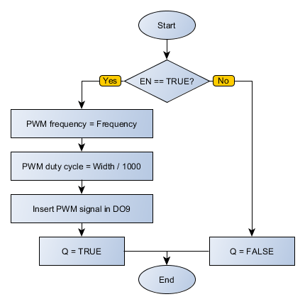
This block, when it has a TRUE value in EN, inserts into the selected output a PWM signal with a frequency determined in Frequency (between 0 and 300 kHz) and pulse width determined by Width (between 0 and 1000, where 1000 would be 100% cycle active).
|
NOTE! This block has priority over any coil that is writing data to the selected output. |
The ENO value forwards to the next Ladder block the EN value after the operation is completed.
Block Flowchart
Example in Ladder
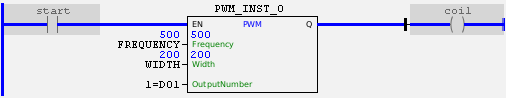
The above example enables a PWM signal in DO1 with a frequency of 500 Hz and a duty cycle of 20%. The block ends with success; Q output is activated.
Example in ST
The example below displays instructions for applying the example above in ST language.
VAR FREQUENCY : UDINT := 500; WIDTH : UINT := 200; start : BOOL := 0 ; coil : BOOL; PWM_INST_0 : FB_PWM; END_VAR
PWM_INST_0.EN := start; PWM_INST_0(Frequency:=FREQUENCY, Width:=WIDTH, OutputNumber:=1); coil := PWM_INST_0.Q;
|
|---|