|
CTUD Count Up/Down Counter |
  
|
|
CTUD Count Up/Down Counter |
|
Block for gradual count and countdown of input pulses.
Ladder Representation
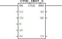
Block Structure
Variable Type |
Name |
Data Type |
Description |
VAR_INPUT |
EN |
BOOL |
Block enabling |
CU |
BOOL |
Pulse identifier for incremental |
|
CD |
BOOL |
Pulse identifier for decremental |
|
R |
BOOL |
Loads the zero value in CV |
|
LD |
BOOL |
Loads the value of PV in CV |
|
PV |
WORD UINT |
Reference value |
|
VAR_OUTPUT |
ENO |
BOOL |
Output enabling |
QU |
BOOL |
Counter overrun flag |
|
QD |
BOOL |
Counter zeroed flag |
|
CV |
WORD UINT |
Current count value |
|
VAR |
CTUD_INST_0 |
CTUD |
Instance of access to block structure |
|
NOTE!
Some devices allow you to configure user parameters, but these need to be configured for use in the fields PV and CV, where it is necessary to select a compatible data type (WORD or UINT). For more information refer to the corresponding topic. |
Operation
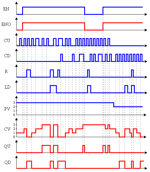
When this block has a TRUE value in EN, it acts as a CTD block and block CTU at the same time acting on the same CV counter. That is: increments CV until it reaches PV to the leading edges in CU and decrements CV until it reaches zero to the leading edges in CD. A positive transition in R carries zero in CV, while a leading edge in LD loads the PV value in CV. If CV has zero value, QD receives TRUE, and if CV has value equal to PV, QU receives TRUE.
The ENO value forwards to the next Ladder block the EN value.
Block Flowchart

Operation Diagram
Example in Ladder

The example above shows the disabled block, with all its internal variables zeroed. Although the external controls are activated, these values are not forwarded to the instance of the block.
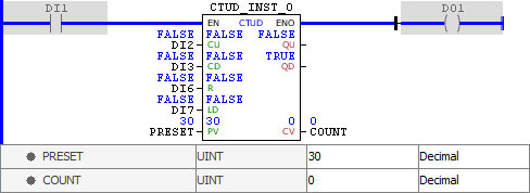
When activated, the block identifies the value of PRESET, loading it in PV, and identifies that the output is at zero, enabling the QD output. When execution is completed, the ENO output is activated.

At each leading edge identified in CU, the value of CV is incremented until it reaches the PV value, when the QU output is enabled. When execution is completed, the ENO output is activated.

At each leading edge detected in CD, the CV value is decremented. When CV is a value between zero and PV, both QD and QU outputs are deactivated. When execution is completed, the ENO output is activated.

A TRUE value in R resets CV, while a TRUE value in LD loads the value of PV to CV. As we can see, R prevails over LD, leaving CV and enabling the QD output. When execution is completed, the ENO output is activated.
Example in ST
The example below displays the instructions for applying the example above in the ST language.
VAR PRESET : UINT := 30; COUNT : UINT; CTUD_INST_0 : FB_CTUD; END_VAR
CTUD_INST_0.EN := DI1; CTUD_INST_0( CU:=DI2, CD:=DI3, R:=DI6, LD:=DI7, PV:=PRESET); COUNT := CTUD_INST_0.CV; DO1 := CTUD_INST_0.ENO;
|
|---|