|
PID2 Controlador Proporcional-Integral-Derivativo com Sintonia Automática (Auto Tuning) |
  
|
|
PID2 Controlador Proporcional-Integral-Derivativo com Sintonia Automática (Auto Tuning) |
|
Block that performs auto tuning of a discrete PID controller. From the input variables, it calculates the corresponding controller output PID or PI throw relay method. This block also implements the obtained controller or another that the user wishes.
Ladder Representation
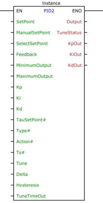
Block Structure
Variable Type |
Name |
Data Type |
Description |
VAR_INPUT |
EN |
BOOL |
Block enable |
SetPoint |
REAL |
Automatic reference (pre-control) |
|
ManualSetPoint |
REAL |
Forced reference (post-control) |
|
SelectSetPoint |
BOOL |
Select which reference to use |
|
Feedback |
REAL |
Mesh Feedback Variable |
|
MinimumOutput |
REAL |
Minimum value of controller output |
|
MaximumOutput |
REAL |
Maximum value of controller output |
|
Kp |
REAL |
Proportional gain |
|
Ki |
REAL |
Integral gain |
|
Kd |
REAL |
Derivative Gain |
|
TauSetPoint# |
REAL |
Auto reference input filter time constant |
|
Type# |
BYTE |
Controller Type |
|
Action# |
BYTE |
Control action |
|
Ts# |
UINT |
Sampling period [ms] |
|
Tune |
BYTE |
It starts the tuning process according to Table 2 |
|
Delta |
REAL |
Parameter of the method of the relays that represents the variation of the manipulated variable with respect to the value that reached the reference. |
|
Hysteresis |
REAL |
Determines the hysteresis in the switching of the Relay |
|
TuneTimeOut |
DWORD |
Maximum wait time until tuning is complete [ms] |
|
VAR_OUTPUT |
ENO |
BOOL |
Output enable |
Output |
REAL |
Controller Output |
|
TuneStatus |
BYTE |
Automatic tuning status as per Table 3 |
|
KpOut |
REAL |
Proportional gain obtained in tuning |
|
KiOut |
REAL |
Full gain achieved in tuning |
|
KdOut |
REAL |
Derivative gain obtained in tuning |
|
VAR |
PID2_INST_0 |
PID2 |
Block Structure Access Instance |
Table1
Operation
The operation of the PID2 block is divided into two parts: Control and Automatic Tuning.
The Tune variable defines which mode of operation. Whenever Tune = 0, the system operates in control mode, with values of the user defined gains, in the same way as the PID block.
The control part is exactly the same as the PID block, see the PID Help.
When Tune receives a value other than 0, the automatic tuning process starts. Some rules need to be obeyed so that tuning can occur. They will be displayed in the sequence.
The Auto-Tuning
For the Automatic Tuning, the Relay Method is used, which is based on obtaining the critical gain ![]() and critical period
and critical period ![]() , which can be used to obtain PID controller gains through several tuning rules: Ziegler-Nichols, Ciancone-Marlin, Tyreus- Luyben, ITAE, among others.
, which can be used to obtain PID controller gains through several tuning rules: Ziegler-Nichols, Ciancone-Marlin, Tyreus- Luyben, ITAE, among others.
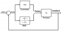
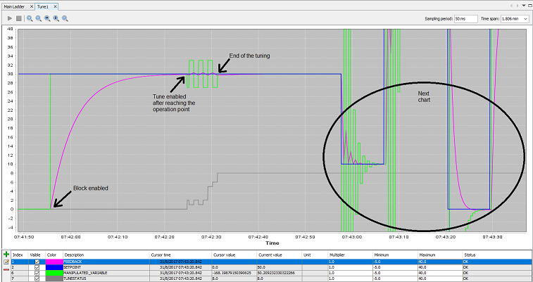
During the tuning process, the control is switched off and a "relay" determines the output of the controller (Output), as shown below.
At start, the relay (Output) goes to the value![]() and after a period
and after a period ![]() the output
the output![]() (Feedback) starts to increase. When the output becomes higher than the value of the setpoint + hysteresis, the relay switches to
(Feedback) starts to increase. When the output becomes higher than the value of the setpoint + hysteresis, the relay switches to![]() , and so on, as shown below.
, and so on, as shown below.
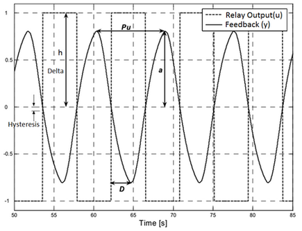
Since the ![]() value of the manipulated variable (Output) stabilized at the point of operation, we have:
value of the manipulated variable (Output) stabilized at the point of operation, we have:
![]()
In the case of image above, ![]()
From the obtained subtraction curve, the necessary parameters are obtained to obtain the controller.
Criteria for tuning to be performed
In order for automatic tuning to be performed properly, two criteria must be obeyed:
1) place the system at the operating point to be calibrated (the difference must be less than 20%);
2) variable ![]() , which is the manipulated variable, may not be showing oscillation greater than 20%;
, which is the manipulated variable, may not be showing oscillation greater than 20%;
OBS: you can use the Manual mode of the block to reach the operating point without large oscillations (via the variable ![]() ).
).
Step by step to perform tuning (portuguese only)
1) ![]() must start with the value zero;
must start with the value zero;
2) Set a value for ![]() . An initial value of 10% of the manipulated variable value is recommended (
. An initial value of 10% of the manipulated variable value is recommended (![]() ) which reached the system setpoint;
) which reached the system setpoint;
Ex: Assuming that to stabilize at the point of operation![]() = 12.3. In this case, use
= 12.3. In this case, use ![]()
3) Set an initial value for ![]() . This value should be slightly larger than the noise present in the system. An initial value of 2% of the Setpoint value can be used if no noise is known;
. This value should be slightly larger than the noise present in the system. An initial value of 2% of the Setpoint value can be used if no noise is known;
Ex: for ![]() = 60.0, use
= 60.0, use ![]()
4) Set a value in milliseconds (![]() ) to
) to ![]() . This value depends on the system being applied to the block. Slower systems will require a longer time. It should be sufficient for at least 10 cycles of the relay to be complete, although with 5 cycles the system generally already stabilizes;
. This value depends on the system being applied to the block. Slower systems will require a longer time. It should be sufficient for at least 10 cycles of the relay to be complete, although with 5 cycles the system generally already stabilizes;
5) Place the system in the operating point. If a pre-control has already been done, it can be applied. Another option is to use the manual mode and vary input ![]() until the system stabilizes at the point of operation, that is,
until the system stabilizes at the point of operation, that is, ![]() as close as possible to
as close as possible to ![]() ;
;
6) Enable tuning by choosing the type of control (PI or PID and the rule used) through the variable ![]() , as shown in Table 2;
, as shown in Table 2;
7) The output ![]() will inform you the status of the automatic tuning process, as shown in Table 9. At the end of the process, the output
will inform you the status of the automatic tuning process, as shown in Table 9. At the end of the process, the output ![]() value will be received if the calibration is performed successfully and the outputs
value will be received if the calibration is performed successfully and the outputs ![]() ,
, ![]() and
and ![]() will be updated with the values obtained in the tuning process.
will be updated with the values obtained in the tuning process.
Tune |
Controller |
0 |
Disabled |
1 |
Automatic PID Controller |
2 |
Automatic PI Controller |
3 |
Tyreus-Luyben PID Controller |
4 |
Tyreus-Luyben PI Controller |
5 |
PID ITAE Controller |
6 |
PI ITAE Controller |
7 |
Ciancone-Marlin PID Controller |
8 |
Ciancone-Marlin PI Controller |
9 |
Ziegler-Nichols PID Controller |
10 |
Ziegler-Nichols PI Controller |
Table 2
Tune Status |
Meaning |
0 |
Disabled |
1 |
High level relay |
2 |
Low level relay |
4 |
Stabilized system |
5 |
Stable and Relay at high level |
6 |
Stable and Relay at low level |
8 |
Tuning completed |
16 |
Reserved |
32 |
Timeout |
64 |
Method nonexistent |
128 |
Busy: another block in tune |
Table 3
The Tyreus-Luyben methods are recommended for systems with the dominant time constant in relation to the transport delay. Ciancone-Marlin methods are recommended for systems with a long transport delay. The minimum ITAE method is for intermediary situations.
It is recommended for initial tuning or for users without some practice with the method of the relays, the use of automatic 1 or 2 for ![]() , leaving the system to choose the most appropriate way.
, leaving the system to choose the most appropriate way.
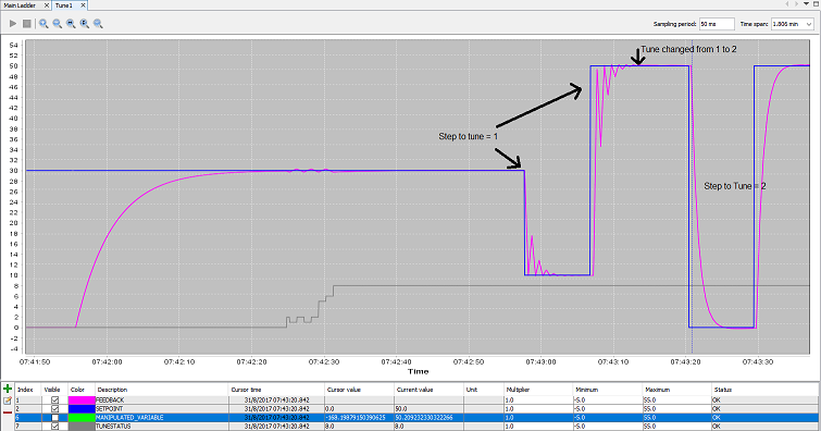
After tuning, the method can be changed causing a new controller to be calculated without re-tuning, since the required data is stored internally. This allows other methods to be easily experienced.
For a new tuning to be made, ![]() need to receive the value zero.
need to receive the value zero.
Block Flowchart
N/A
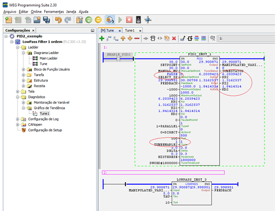
Example in Ladder
Example in ST
The example below displays the instructions for applying the example above in the ST language.
VAR SETPOINT : REAL := 30.0; MANUAL_MV : REAL := 30.0; SELECT_SP : BOOL := FALSE; FEEDBACK : REAL; KP2 : REAL := 6.2039423; KI2 : REAL := 1.3162537; KD2 : REAL := 1.8414314; TUNEENABLE2 : BYTE; DELTA : REAL; HISTERESE : REAL; MANIPULATED_VARIABLE : REAL; TUNESTATUS : BYTE; PID2_INST_1 : FB_PID2; TAU : REAL := 5.0; LOWPASS_INST_3 : FB_LOWPASS; END_VAR
PID2_INST_1.EN := DI1; PID2_INST_1( SetPoint:=SETPOINT, ManualSetPoint:=MANUAL_MV, SelectSetPoint:=FALSE, Feedback:=FEEDBACK, MinimumOutput:=-1000, MaximumOutput:=1000, Kp:=KP2, Ki:=KI2, Kd:=KD2, TauSetPoint:=0.0, Type:=1, Action:=0, Ts:=500, Tune:=TUNEENABLE2, Delta:=DELTA, Hysteresis:=HISTERESE, TuneTimeOut:=1800000); MANIPULATED_VARIABLE := PID2_INST_1.Output; TUNESTATUS := PID2_INST_1.TuneStatus; KP2 := PID2_INST_1.KpOut; KI2 := PID2_INST_1.KiOut; KD2 := PID2_INST_1.KdOut;
LOWPASS_INST_3( EN:=TRUE, Input:=MANIPULATED_VARIABLE, Tau:=TAU, Ts:=10); FEEDBACK := LOWPASS_INST_3.Output;
|
|---|