|
Overview |
  
|
|
Overview |
|
The trace function is used to register variables* of interest of the device (such as current, voltage, speed, etc.) when a certain event occurs in the system. Since it triggers the storage of the variables, in the system this event is called trigger, and the user can define up to three trigger conditions and the logic to be used in them (AND or OR logic).
The stored variables can be seen as graphics by using the WPS running on a PC connected via USB or via serial to the device.
NOTE: Up to 6 (six) channels using SCA06; Up to 4 (four) channels using CFW-11.
Below is an overview of the configuration screen of the trace function (example using SCA06).
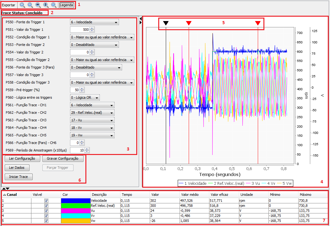
| 1. | Graphic Zoom. This bar contains the options to control the graphic, such as export to image file, zoom in, zoom out, set width, set height, se all and show or not show the graphic lettering. |
| 2. | Trace Status. This item shows the present status of the trace function: not started, trigger occurred and concluded. |
| 3. | Parameters. In this part are all the parameters that can be configured in the trace routine, such as triggers, conditions, channels to be monitored and sampling period. |
| 4. | Graphic. In this area is the graphic after the conclusion of trace. In the lower part is the time line and on the right are the values separated by unit of measurement. |
| 5. | Markers. The markers are within the graphic area. After the graphic is set, just click on the black marker to create red markers (fixed). It is possible to add two fixed markers. Those fixed markers are used to calculate the average and effective values between the two points. |
| 6. | Trace command. Below is the description of the command functions: |
| 6.1. | Read configuration: It reads the trace configuration parameters and updates the parameters on the screen (item 3). |
| 6.2. | Save configuration: It sends the trace configuration parameters (item 3) to the equipment. |
| 6.3. | Read Data: Command used only when the trace status is concluded, that is, there is already a concluded trace on the equipment, and you just wish to download the data without starting a new trace. |
| 6.4. | Force Trigger: Forces the trigger regardless the conditions. |
| 6.5. | Start Trace: It starts the trace function. |
| 7. | Channel Table. This table shows the data of the chosen channels, besides the possibility to hide channels (Visible), change the channel color (Color) and set the graphic limits per unit of measurement (Maximum). |