|
TP Pulse Timer |
  
|
|
TP Pulse Timer |
|
Timer block that, when identifies it is energized, enables the output after a delay set by PT.
Ladder Representation
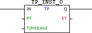
Block Structure
Variable Type |
Name |
Data Type |
Description |
VAR_INPUT |
IN |
BOOL |
Block enabling |
PT |
WORD UINT DWORD1 UDINT1 |
Time while the output is enabled |
|
TIMEBASE |
WORD |
Time base for PT and ET |
|
VAR_OUTPUT |
Q |
BOOL |
Block output |
ET |
WORD UINT DWORD1 UDINT1 |
Counter elapsed time |
|
VAR |
TP_INST_0 |
TP |
Instance of access to block structure |
|
NOTE! 1. In CFW300 and CFW100, the PT and ET field types can only be WORD or UINT. 2. Some devices allow you to configure user parameters, but these need to be configured for use in the fields PT and ET, where it is necessary to select a compatible data type as shown in table above. For more information refer to the corresponding topic; 3) The TIMEBASE field may vary depending on the device used. |
Operation
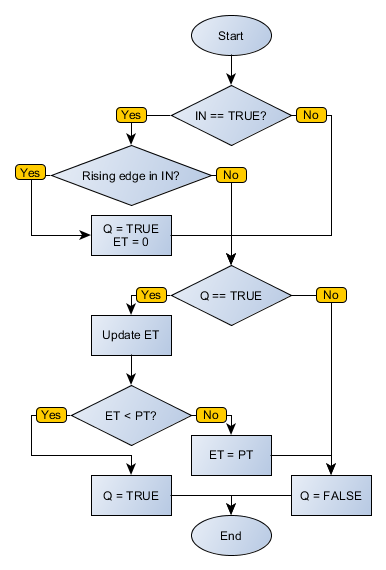
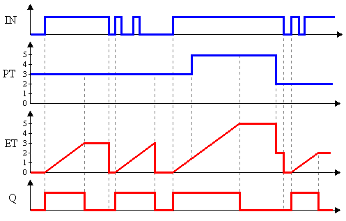
On the edge positive transition in IN, Q receives TRUE value, counting is triggered and ET is incremented according to TIMEBASE. When ET equals PT, the Q output goes to state FALSE until IN revolutions to FALSE. At that moment, if IN is at TRUE level, nothing happens. On the edge positive transition in IN, ET is automatically reset.
Compatibility
Device |
Version |
PLC300 |
1.50 or higher |
SCA06 |
2.00 or higher |
Block Flowchart
Operation Diagram
Example in Ladder
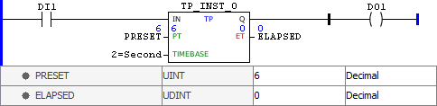
The above example enables the DO1 output for six seconds at each DI1 positive transition.
Example in ST
The example below displays the instructions for applying the example above in the ST language.
VAR PRESET : UINT := 6; ELAPSED : UDINT; TP_INST_0 : FB_TP; END_VAR
TP_INST_0.IN := DI1; TP_INST_0(PT:=PRESET, TIMEBASE:=2); // TIMEBASE according to ELAPSED := TP_INST_0.ET; // the device used DO1 := TP_INST_0.Q;
|
|---|