PID
The PID block executes a discrete proportional-integral-derivative controller. It calculates the controller output from the configured input variables.
Ladder Representation

Variable Table
| Variable Type | Name | Data Type | Description |
|---|---|---|---|
| VAR_INPUT | EN | BOOL | Block enable. |
| VAR_INPUT | SetPoint | REAL | Automatic reference before control. |
| VAR_INPUT | ManualSetPoint | REAL | Forced reference after control. |
| VAR_INPUT | SelectSetPoint | BOOL | Selects which reference to use. |
| VAR_INPUT | Feedback | REAL | Loop feedback variable. |
| VAR_INPUT | MinimumOutput | REAL | Minimum controller output value. |
| VAR_INPUT | MaximumOutput | REAL | Maximum controller output value. |
| VAR_INPUT | Kp | REAL | Proportional gain. |
| VAR_INPUT | Ki | REAL | Integral gain. |
| VAR_INPUT | Kd | REAL | Derivative gain. |
| VAR_INPUT | TauSetPoint# | REAL | Time constant for the automatic-reference input filter. |
| VAR_INPUT | Type# | BYTE | Controller type. |
| VAR_INPUT | Action# | BYTE | Control action. |
| VAR_INPUT | Ts# | UINT | Sampling period, in milliseconds. |
| VAR_OUTPUT | ENO | BOOL | Output enable. |
| VAR_OUTPUT | Output | REAL | Controller output. |
| VAR | PID_INST_0 | PID | Instance used to access the block structure. |
Operation
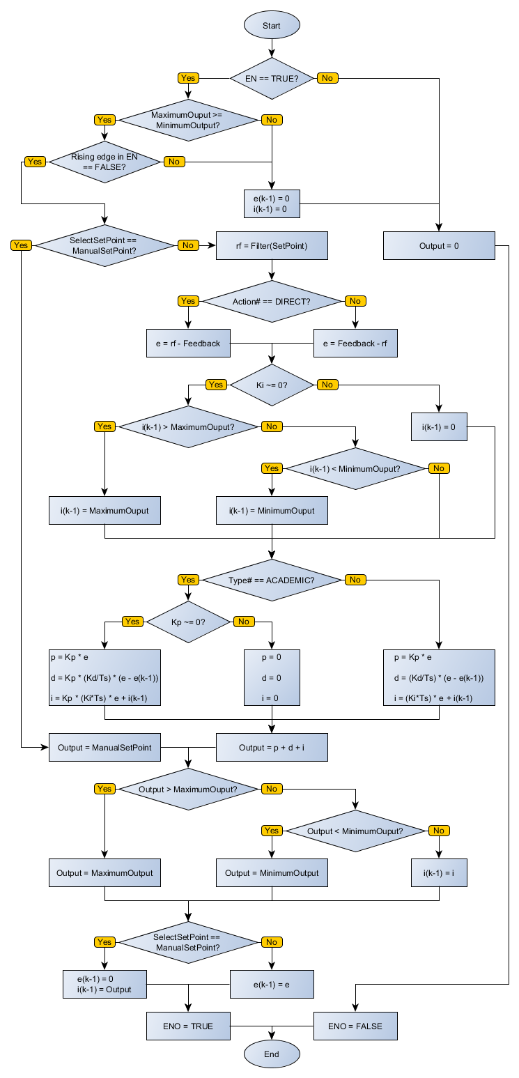
On the rising edge of EN, Output receives zero. The block executes while EN remains TRUE.
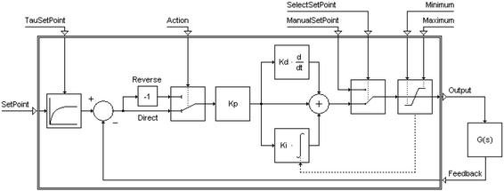
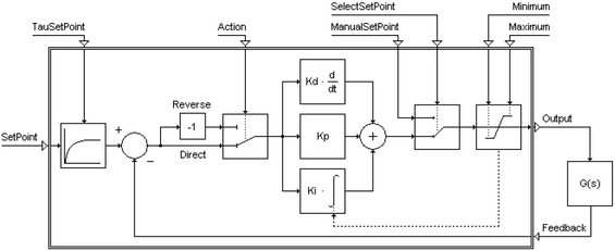
When enabled, the block executes a PID control routine using the configured Kp, Ki, and Kd values. The selected Type# defines whether the academic topology or the parallel topology is used.
MinimumOutput and MaximumOutput saturate the controller output. When SelectSetPoint is FALSE, the block uses SetPoint as the reference and the controller acts on the process. When SelectSetPoint is TRUE, the controller no longer acts on the process and ManualSetPoint is used as the controller output signal.
Action# defines the feedback operation. With direct action, the operation is SetPoint - Feedback. With reverse action, the operation is Feedback - SetPoint.
Feedback receives the process variable used as the plant output. Ts# receives the controller sampling period. TauSetPoint# receives the time constant for the automatic-reference input filter.
When EN is FALSE, Output remains unchanged. After operation is complete, ENO passes the value of EN to the next Ladder block.
The following diagrams show the controller topologies referenced by the block operation.
Reducing Kp usually makes the process slower, generally more stable or less oscillatory, and reduces overshoot. Increasing Kp usually makes the process respond faster, but may make it unstable or more oscillatory and increase overshoot.
Reducing Ki usually makes the process slower to reach the setpoint, generally more stable or less oscillatory, and reduces overshoot. Increasing Ki usually makes the process reach the setpoint faster, but may make it more unstable or oscillatory and increase overshoot.
Reducing Kd usually makes the process slower and reduces overshoot. Increasing Kd may increase overshoot.
For academic PID control, use the following adjustment guidance from the source documentation:
- If the process is almost correct but overshoot is slightly high, try reducing
Kpby 20%, reducingKiby 20%, or reducingKdby 50%. - If the process is almost correct but has no overshoot and takes too long to reach the setpoint, try increasing
Kpby 20%, increasingKiby 20%, or increasingKdby 50%. - If the process performance is good but the process output varies too much, try increasing
Kdby 50% or reducingKpby 20%. - If the process performance is poor and the transient response lasts for several oscillation periods that decrease very slowly or do not decrease, try reducing
Kpby 50%. - If the process moves slowly toward the setpoint, has no overshoot, is still far from the setpoint, and the process output is lower than the nominal value, try increasing
Kpby 50%, increasingKiby 50%, or increasingKdby 70%.
Execution Flowchart
Examples
- Ladder Example
- Structured Text Example

The Ladder example creates a digital academic PID loop with a 50 ms sampling time. It uses the KP, KI, and KD constants for control.
The example uses the automatic reference SETPOINT, filtered by a first-order filter with a 0.01 time constant. The error signal is calculated as the difference between the filtered reference and SAIDA_PLANTA. The controller output is saturated between 0.1 and 2.5 and written to ENTRADA_PLANTA.
The following Structured Text code applies the same logic shown in the Ladder example.
VAR
    SETPOINT, SAIDA_PLANTA, ENTRADA_PLANTA : REAL;
    KP : REAL := 6.2;
    KI : REAL := 1.3;
    KD : REAL := 1.8;
    PID_INST_2 : FB_PID;
END_VAR

PID_INST_2.EN := DI1;
PID_INST_2(
    SetPoint:=SETPOINT,
    ManualSetPoint:=1,
    SelectSetPoint:=FALSE,
    Feedback:=SAIDA_PLANTA,
    MinimumOutput:=0.1,
    MaximumOutput:=2.5,
    Kp:=KP,
    Ki:=KI,
    Kd:=KD,
    TauSetPoint:=0.01,
    Type:=0,
    Action:=0,
    Ts:=50);
ENTRADA_PLANTA := PID_INST_2.Output;
DO1 := PID_INST_2.ENO;