|
MC_GearIn Speed Synchronism |
  
|
|
MC_GearIn Speed Synchronism |
|
Block responsible for execution of the synchronism in speed between the programmed axes.
Ladder Representation
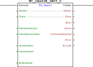
Execution Features
Program Memory Size |
74 Bytes |
Data Memory Size |
28 Bytes |
Block Structure
Variable Type |
Name |
Data Type |
Description |
VAR_IN_OUT |
Master |
BYTE |
Selection of operation master (0 - Fast digital inputs) (1 - CANopen) (2 - Encoder 1) (3 - Virtual Axis) (4 - Encoder 2) |
Slave |
BYTE |
Selection of operation slave (0 - Real axis) (1 - Virtual 1 axis) |
|
VAR_INPUT |
Execute |
BOOL |
Block enabling |
RatioNumerator |
INT |
Numerator of the synchronism ratio |
|
RatioDenominator |
WORD |
Denominator of the synchronism ratio |
|
Acceleration |
REAL |
Acceleration [rpm / s] |
|
Deceleration |
REAL |
Deceleration [rpm / s] |
|
BufferMode |
BYTE |
Execution start mode (0 - Starts block immediately, if there is another block in the execution it will be aborted) (1 - When another block is in execution, the block in execution will continue its motion until the end and this new block will wait to be executed.) (6 – If another block is in execution, this block will go into error 52 and will not be executed. The HMI will show the alarm A00052.) |
|
VAR_OUTPUT |
InGear |
BOOL |
Output enabling |
Busy |
BOOL |
Flag indicating the block has not yet been ended |
|
Active |
BOOL |
Block flag with control on the axis |
|
CommandAborted |
BOOL |
Flag of aborted command |
|
Error |
BOOL |
Error in the execution flag |
|
ErrorID |
WORD |
Identifier of the occurred error |
|
VAR |
MC_GEARIN_INST_0 |
MC_GEARIN |
Instance of access to block structure |
Operation
When this block detects a leading edge on Execute, it sends a command for synchronism in speed between the programmed axes.
For the slave axis to reach the speed of the master axis, a motion will be performed with an acceleration/deceleration configured in the "Acceleration" and "Deceleration" arguments. The motion direction will depend on the signal of the RatioNumerator. If RatioNumerator is greater than zero, the motion will be in the same direction as the master axis, and if the RatioNumerator is smaller than zero, the motion will be in the opposite the direction of the master axis.
The InGear output is activated when the sync is achieved. It order to finish the block, it is necessary to execute another block or the changing of the drive to the Disabled or Errorstop status.
If there is any error in the execution, the Error output is enabled and ErrorID displays an error code according to the table below.
Code |
Description |
52 |
Attempt to execute block with BufferMode in Single when another block is active. |
62 |
Acceleration programmed below the minimum allowed. |
63 |
Acceleration programmed above the maximum allowed. |
64 |
Deceleration programmed below the minimum allowed. |
65 |
Deceleration programmed above the maximum allowed. |
67 |
Drive in the "Disabled" or "Errorstop" status. |
69 |
Drive in the "Stopping" status. |
70 |
Attempt to execute block with BufferMode in Buffered when another block is active and another block is waiting. |
71 |
P202 different from 4. |
72 |
Invalid synchronism ratio. |
74 |
Drive in the "Homing" status. |
78 |
MC block not executed – Internal fault. |
Example in Ladder
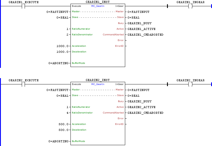
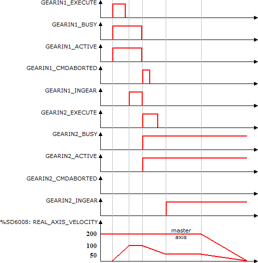
In the up transition of GEARIN1_EXECUTE, the first MC_GearIn block is executed. With this the Busy Active and this block signals are set and the search of synchronization with the configured acceleration begins. As the ratio configured is 1:2 and the master axis is at 200 RPM, the slave axis must reach 100 RPM to establish the synchronism.
At the moment in which the speed reaches 100 RPM, the InGear output is set.
With the transition of rising GEARIN2_EXECUTE, the second MC_GearIn block is instantly executed. With this the Busy Active signals of this block are set and the search of synchronization with the configured acceleration begins. As the ratio configured is 1:4 and the master axis is at 200 RPM, the slave axis must reach 50 RPM to establish the synchronism. At the same time, the Busy, Active and InGear signals of the first block are reset and the CommandAborted signal is set for 1 scan.
When the speed of 50 RPM is reached, the InGear output of the second block is set and remains until the execution of other block.
Example in ST
The example below displays the instructions for applying the example above in the ST language.
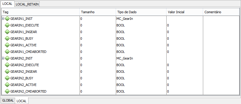
VAR GEARIN1_EXECUTE, GEARIN1_INGEAR, GEARIN2_EXECUTE, GEARIN2_INGEAR, GEARIN1_BUSY, GEARIN1_ACTIVE, GEARIN1_CMDABORTED, GEARIN2_BUSY, GEARIN2_ACTIVE, GEARIN2_CMDABORTED : BOOL; GEARIN1_INST, GEARIN2_INST : FB_MC_GearIn; END_VAR
GEARIN1_INST.Execute := GEARIN1_EXECUTE; GEARIN1_INST( Master:=0, Slave:=0, RatioNumerator:=1, RatioDenominator:=2, Acceleration:=1000.0, Deceleration:=1000.0, BufferMode:=0); GEARIN1_BUSY := GEARIN1_INST.Busy; GEARIN1_ACTIVE := GEARIN1_INST.Active; GEARIN1_CMDABORTED := GEARIN1_INST.CommandAborted; GEARIN1_INGEAR := GEARIN1_INST.InGear;
GEARIN2_INST.Execute := GEARIN2_EXECUTE; GEARIN2_INST( Master:=0, Slave:=0, RatioNumerator:=1, RatioDenominator:=4, Acceleration:=500.0, Deceleration:=500.0, BufferMode:=0); GEARIN2_BUSY := GEARIN2_INST.Busy; GEARIN2_ACTIVE := GEARIN2_INST.Active; GEARIN2_CMDABORTED := GEARIN2_INST.CommandAborted; GEARIN2_INGEAR := GEARIN2_INST.InGear;
|
|---|