|
MW_PlcSpeed1 |
  
|
|
MW_PlcSpeed1 |
|
Block for speed control with ramp generation and specified number of pulses.
Ladder Representation
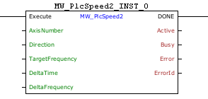
Block Structure
Variable Type |
Name |
Data Type |
Description |
VAR_INPUT |
EN/Execute |
BOOL |
Block enabling |
AxisNumber |
CONST |
Selected axis |
|
Direction |
BOOL |
Movement direction |
|
TargetFrequency |
DWORD DINT |
Final pulse frequency [Hz] |
|
DeltaTime |
DWORD |
Step time until reaching the target frequency [ms] |
|
DeltaFrequency |
DWORD DINT |
Frequency variation of each step [Hz] |
|
VAR_OUTPUT |
DONE |
BOOL |
Output enabling |
Active |
BOOL |
Indicates that the block is active |
|
Busy |
BOOL |
Indicates that another block is using the selected output |
|
Error |
BOOL |
Indicates that an error occurred when calling the block |
|
ErrorID |
BYTE |
Indicates the error generated |
|
VAR |
MW_PlcSpeed2_INST_0 |
MW_PlcSpeed2 |
Instance of access to block structure |
Operation
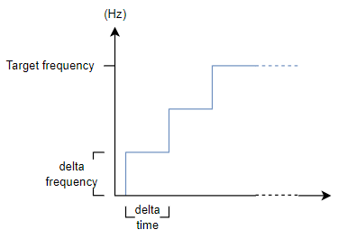
This block, when it detects a rising edge on the EN input, starts generating pulses for the selected axis with a frequency starting from 0 Hz up to the desired frequency (targetFrequency) (between 0 and 300 kHz).
At each time step (deltaTime), the frequency is incremented by deltaFrequency until it reaches the desired frequency (targetFrequency).
The pulses are only interrupted when a Stop block is called.
While a Stop block is not called, the "Active" output remains at a high level.
When EN is FALSE, DONE remains FALSE. The DONE output is activated when the block successfully completes execution (Stop block called), remaining at a TRUE level until EN becomes FALSE.
The minimum number of pulses that can be generated is 2.
If this limitation is not respected, no pulse is generated.
The minimum number of pulses that can be generated per step is 2.
If this limitation is not respected, the frequency ramp is not generated; in other words, upon enabling the block, the pulse frequency starts directly at the targetFrequency value.
The MW_PlcChangeSpeed block can be used in conjunction to change the output frequency during the execution of this block. Refer to the help section of the MW_PlcChangeSpeed block for more information.
|
NOTE! If other PWM blocks running use the same output, the one called first will have priority and the "Busy" output is set. |
The figure below shows the default operation of the block, without using the MW_PlcChangeSpeed block together.
If there is any error in the execution, the Error output is enabled and ErrorID displays an error code according to the table below.
Code |
Description |
0 |
Executed successfully |
1 |
Axis control not enabled |
2 |
Invalid number of steps |
3 |
Invalid ramp |
4 |
Configuration error |
|
NOTE! Stepper motor control must be enabled for the selected axis. Look at the user manual and parameter manual. |
Example in Ladder
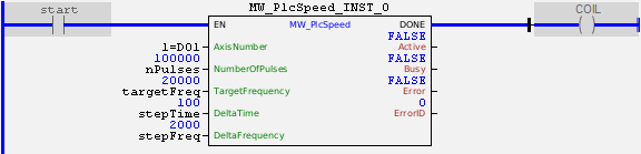
In the example above, the "start" contact enables a pulse signal on axis 1 with an initial frequency of 0 Hz and a duty cycle of 50%. The frequency will be incremented by 2000 Hz every 100ms until it reaches 20000 Hz, meaning the total ramp time will be 1 second. After that, the block will continue generating pulses until a "Stop" block is called.
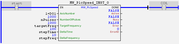
In the example above, the "start" contact enables a pulse signal on axis 1 with an initial frequency equal to targetFreq. The ramp will not be generated because it is not possible to produce 2 pulses at 10 Hz within the 100ms step time. After that, the block will continue generating pulses until a "Stop" block is called.
Example in ST
The example below displays instructions for applying the functional example in ST language.
VAR start : BOOL := 0; nPulses : DWORD := 100000; targetFreq : DWORD := 20000; stepTime : DWORD := 100; stepFreq : DWORD := 2000; MW_PlcSpeed2_INST_0 : FB_MW_PlcSpeed2; END_VAR
MW_PlcSpeed2_INST_0.EN := start; MW_PlcSpeed2_INST_0( AxisNumber:=1, Direction:=false, TargetFrequency:=targetFreq, DeltaTime:=stepTime, DeltaFrequency:=stepFreq); COIL := MW_PlcSpeed2_INST_0.DONE;
|
|---|