|
MW_PlcMoveAbsolute1 |
  
|
|
MW_PlcMoveAbsolute1 |
|
Block for absolute position control with stepper motors.
Ladder Representation

Block Structure
Variable Type |
Name |
Data Type |
Description |
VAR_INPUT |
EN/Execute |
BOOL |
Block enabling |
AxisNumber |
CONST |
Selected axis |
|
Position |
DINT |
Desired position |
|
VAR_OUTPUT |
DONE |
BOOL |
Output enabling |
Active |
BOOL |
Indicates that the block is active |
|
Busy |
BOOL |
Indicates that another block is using the selected output |
|
Error |
BOOL |
Indicates that an error occurred when calling the block |
|
ErrorID |
BYTE |
Indicates the error generated |
|
VAR |
MW_PlcMoveAbsolute1_INST_0 |
MW_PlcMoveAbsolute1 |
Instance of access to block structure |
Operation
This block, when it detects a rising edge on the EN input, starts generating the number of pulses (position) required for the stepper motor of the selected axis to reach the desired absolute position.
The PLC has a standard final frequency and acceleration ramp for axis control, which can be changed using the MW_PlcChangeRamp1 block. The default ramp values are:
| • | Acceleration/deceleration time: 100ms; |
| • | Number of steps for acceleration: 20; |
| • | Starting frequency: 0 Hz; |
| • | Final frequency: 10 kHz. |
|
NOTE! There must be enough pulses for the ramp to be generated, otherwise the pulses will be generated without a ramp. |
The "position" entry is always absolute. For example, if the current position is 20000 and "position" is 5000, the ending position will be 5000. In this case, 15000 pulses will be generated at the axis pulse output and the axis direction output signal will be inverted.
|
NOTE! You can reverse the default direction using the product parameters. Look at the parameter manual. |
As long as the desired position is not reached, the "Active" output goes to TRUE.
When EN is FALSE, DONE remains FALSE. The DONE output is activated when the block completes execution successfully, remaining TRUE until EN becomes FALSE.
To stop pulse generation during movement, use the MW_PlcStop1 block. In this case, the block considers the movement to be completed.
The minimum number of steps that can be generated is two. However, if the number of pulses to be generated is zero, the block will return success.
If this limitation is not respected, no pulse is generated and the block returns an error.
If there is any error in the execution, the Error output is enabled and ErrorID displays an error code according to the table below.
Code |
Description |
0 |
Executed successfully |
1 |
Axis control not enabled |
2 |
Invalid number of steps |
3 |
Invalid ramp |
4 |
Configuration error |
|
NOTE! Stepper motor control must be enabled for the selected axis. Look at the user manual and parameter manual. |
Example in Ladder
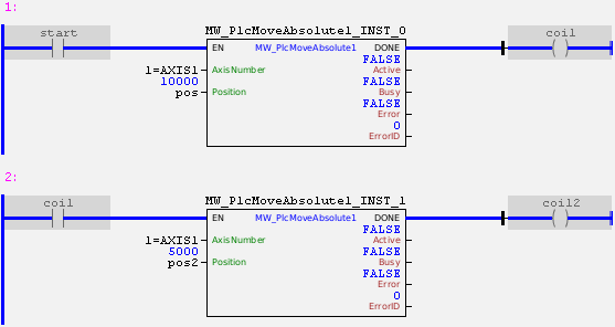
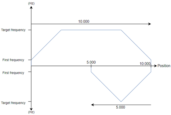
In the example above, the "start" contact enables a PWM signal at the pulse output of axis 1 with an initial frequency of 0 Hz and duty cycle of 50%. The direction output of axis 1 is set to a low level (considering that the direction was not reversed via parameters). The frequency will be increased and decreased according to the standard ramp. At the end of generating 10000 pulses (considering that the initial position was 0), the DONE output is activated and the second block is enabled, starting the generation of -5000 pulses. At this time, the direction output is automatically reversed and 5000 pulses are generated at the pulse output. At the end, the axis will be in position 5000.
Example in ST
The example below displays instructions for applying the functional example in ST language.
VAR pos : DINT := 10000; pos2 : DINT := 5000; start : BOOL := 0 ; coil : BOOL; coil2 : BOOL; MW_PlcMoveAbsolute1_INST_0 : FB_MW_PlcMoveAbsolute1; MW_PlcMoveAbsolute1_INST_1 : FB_MW_PlcMoveAbsolute1; END_VAR
MW_PlcMoveAbsolute1_INST_0.EN := start; MW_PlcMoveAbsolute1_INST_0( AxisNumber:=1, Position:=pos); coil := MW_PlcMoveAbsolute1_INST_0.DONE;
MW_PlcMoveAbsolute1_INST_1.EN := coil; MW_PlcMoveAbsolute1_INST_1( AxisNumber:=1, Position:=pos2); coil2 := MW_PlcMoveAbsolute1_INST_1.DONE;
|
|---|