Block that generates a PWM signal with a certain number of pulses at the selected digital output, following an up and down ramp at the frequency.
Ladder Representation
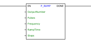
Block Structure
Variable Type |
Name |
Data Type |
Description |
VAR_INPUT |
EN |
BOOL |
Block enabling |
Pulses |
DWORD UDINT |
Total number of pulses of the block execution |
|
Frequency |
DWORD UDINT |
Maximum frequency to be reached |
|
RampTime |
DWORD UDINT |
Ramp time [ms] |
|
Steps |
BYTE USINT |
Steps to increase frequency |
|
OutputNumber |
CONST BYTE |
Output for the signal to be generated |
|
VAR_OUTPUT |
DONE |
BOOL |
Output enabling |
VAR |
P_RAMP_INST_0 |
P_RAMP |
Instance of access to block structure |
Operation
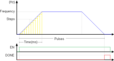
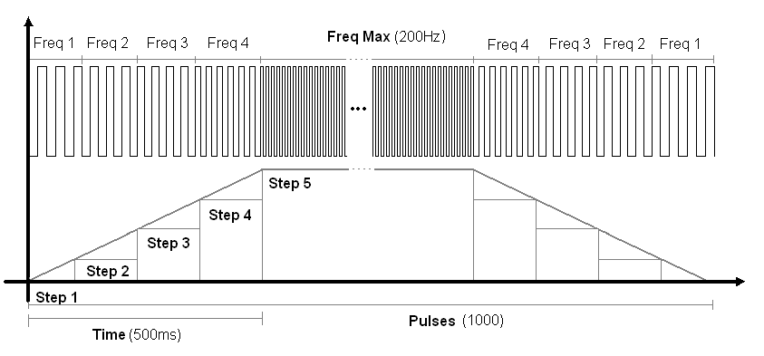
When the EN input is TRUE, the block generates a PWM signal at the selected output. Initially, it generates an up ramp, starting from zero frequency to the Frequency value, based on the Time and Steps settings. At the appropriate moment, the block generates a down ramp, with the same profile as the up ramp, until the frequency is zero and the Pulses value is reached.
When the Pulses value is reached, the DONE output goes to TRUE.
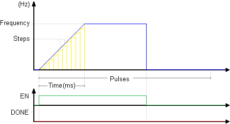
If the EN input goes to FALSE before reaching the number of Pulses, the PWM generation stops immediately.
The duty cycle of the signal remains constant at 0.5 throughout the execution of the block.
For the frequency ramp to be generated, each Step must have at least 2 pulses.
If this limitation is not observed, the frequency ramp is not generated, that is, when the block is enabled, the PWM signal starts directly at the Frequency value.
The minimum number of pulses that can be generated is two. However, if the number of pulses to be generated is zero, the block will return success.
|
NOTE! If other PWM blocks are running, whichever is called first will have priority. |
|
NOTE! This block has priority over any coil that is writing data to the selected output. |
Example in Ladder
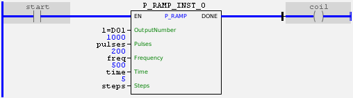
The above example enables a PWM signal in the DO1 output with initial frequency 0 Hz and duty cycle of 50%. The rise time of the ramp frequency is 500 ms, and the ramp has five frequency steps (40, 80, 120, 160 and 200 Hz). In total executing the block, 1000 pulses will be sent to the output. If the block is successfully completed, the DONE output is activated.
Example in ST
The example below displays instructions for applying the example above in ST language.
VAR pulses : DWORD := 1000; freq : DWORD := 200; rampTime : DWORD := 500; steps : BYTE := 5; start : BOOL := 0 ; coil : BOOL; P_RAMP_INST_0 : FB_P_RAMP; END_VAR
P_RAMP_INST_0.EN := start; P_RAMP_INST_0( OutputNumber:=1, Pulses:=pulses, Frequency:= freq, RampTime:=rampTime, Steps:=steps); coil := P_RAMP_INST_0.DONE;
|
|---|